Cable Construction & Dimensional Testing
There are several measurements that are key to a cable's construction and its compliance with relevant standards. These are some of the key cable tests conducted by our expert technicians as part of our internal quality assurance processes but which are also offered as a third-party service to determine compliance against cable standards for cables sourced elsewhere.
Measurement of Insulation Thickness
The measurement of insulation thickness is conducted in accordance with the requirements of the standard BS EN 60811-201. This standard covers the method for measurement of insulation thickness for testing non-metallic materials of all cable types referenced in standards for cable construction and cable materials.
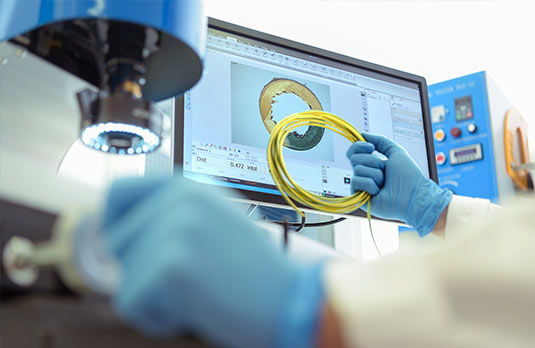
The measurements may be taken using a measuring microscope or profile projector offering at least 10x magnification or an optical digital image analyser. The two types of equipment must be capable of providing a reading accuracy of 0.01mm and an estimated reading to three decimal places when measuring insulation thickness with a specified thickness less than 0.5mm.
The test sample is prepared by removing any covering over the insulation and the conductors the insulation protects. A thin slice is then taken, perpendicular to the longitudinal axis of the conductor (a circular slice) and placed flat under the measuring equipment so that the plane of the slice perpendicular to that of the measuring device lens.
Six measurements are then taken, each approximately 60° from the last. The first of these measurements is at the thinnest point of the insulation wall. The results are evaluated as specified in the relevant cable standard, generally against a required mean value and minimum value.
Insulation thickness is an essential test and determines that there is sufficient insulation material applied whilst also serving as a measure of how concentric that insulation material is. Adequate insulation of the conductor is required to provide sufficient electrical integrity to maintain safety and mechanical strength to protect against stresses on the material.

Measurement of Sheath Thickness
The measurement of sheath thickness in cables is conducted in accordance with the requirements of the standard BS EN 60811-202. This standard covers the method for measurement of sheath thickness for testing non-metallic materials of all cable types referenced in standards for cable construction and for cable materials.
The equipment used to measure the outer sheathing of the cable may be one of the following; a measuring microscope or profile projector of at least 10 x magnification or an optical digital image analyser. The two types of equipment must be capable of providing a reading accuracy of 0.01mm and an estimated reading to three decimal places when measuring insulation thickness with a specified thickness less than 0.5mm.
Cable sheaths may be applied over longitudinally regular surfaces, over longitudinally irregular surfaces or over corrugated metallic sheaths. For sheaths applied over longitudinally irregular surfaces like corrugated metallic sheaths, a micrometre having a ball nose radius of 1mm with an accuracy of 0.01mm may be used.
The preparation of the cable sample for testing is dependent on the sheath application:
Cable sheaths applied over longitudinally regular surfaces: After all materials, if any, inside and outside the sheath have been removed, a thin slice is then taken which is perpendicular to the longitudinal axis of the cable. This is then tested.
Sheathing material applied over longitudinally irregular surfaces: A short piece of sheath is cut perpendicular to the longitudinal axis of the cable, which includes at least one complete pitch of helix formed from the underlying tape. When using a ball nose micrometre, the sample may be left whole, when using a measuring microscope or profile projector, the testing sample piece is prepared by cutting six thin longitudinal slices parallel to the cable axis.
Outer sheaths applied over corrugated metallic sheaths: A sample of cable is taken of sufficient length to include two peaks and two troughs. A reference line is drawn on the outer surface, parallel to the axis of the cable. The position of the minimum thickness is determined on an annular ring taken from the end of the sample, a strip is then cut from the minimum point parallel to the axis of the cable by using the reference line to locate this position.
The measuring procedure for dimensional testing of sheath thickness is in accordance with the sheath application and the results are evaluated as specified in the relevant cable standard, generally against a required mean value and minimum value.
The measurement of sheath thickness is necessary to verify compliance with specifications to meet the mechanical stresses imposed on the cable and ensure safe and reliable performance of the cable during its service life.
Cable Sizing Calculator
Supporting Low Voltage cable sizing to BS and IEC standards with our easy-to-use calculator
Try it now
Custom Cable Design
Tailoring cables to meet bespoke requirements of performance or environmental challenges when off-the-shelf options are unavailable.
Read moreCPD Cable Training
Expert cable tuition from our experts with CPD-certified cable training and tailored cable learning programmes
Courses